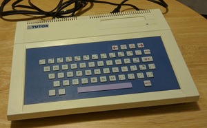
This is a marvelously under explored system from 1982.
I have a US Tomy Tutor, modified with a pico-psu, F18A VGA replacement for the TMS9918 video chip, and a custom built cherry switch keyboard.
I also have a Tomy Pyūta mk II, but the only mods I’ve made to it, are to tap the composite video output. This mod is easily reversable.
My Projects for the Tomy Tutor
The US Tomy Tutor I purchased, mostly worked. The 1 & 2 keys did not work correctly, making it difficult to play games. I tried repairing the pathetic thing, but I just kept making it worse. So I replaced it completely:
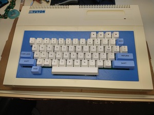
- Tomy Keyboard - replacement PCB for switch based keyboard.
Pico PSU
The power supply inside the US Tomy Tutor was failing, so I replaced it. I used a PICO-PSU. This uses an external AC to 12VDC adapter, borrowed from an old laptop. And then the PICO-PSU passes the 12VDC and adapts down to 5VDC regulated power. The Tomy is also designed to require 12VDC, but this is not used by the computer once the F18A vdp replacement is installed. The original TMS9918 would still require teh 12VDC.
The -5VDC is exposed to the cartridge port, but Tomy cartridges never used it. I suspect this was wishful thinking for adopting TI-99/4A GROM cartridges. So I left this out as well.
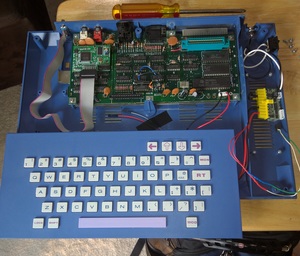
F18A VGA
I haven’t written any software to utilize the F18A on the Tomy yet, but it makes it convenient to hook up to my existing VGA to HDMI setup.
You can see the mod in the previous picture. I removed the original TMS9918 VDP, a couple capacitors for the video ram that where in the way, and the RF modulator.
Player 1 Keyboard controls
The keyboard seems to overlap with the gamepad control port. For Player 1, the keyboard can be used to play the cartridge games:
| Key | Function |
|---|---|
| O | SL |
| P | SR |
| L | down |
| <, | up |
| >. | right |
| +; | left |
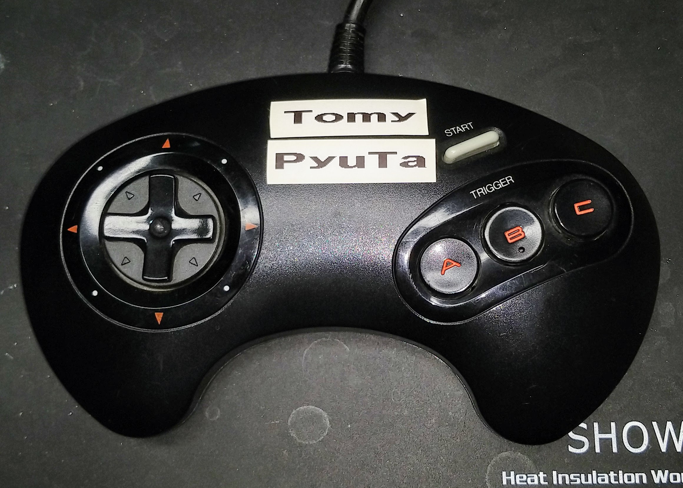
Sega 3-button Genesis/Megadrive rewiring
My first Tomy arrived without any controller, and a mostly broken keyboard. So to try any games, I quickly had to build a controller. I used a Sega 3-button controller for the Genesis or Mega Drive system.
First, remove all the components from the controller. There is one IC, and several passive components.
Also unsolder all the leads to the controller cable. They all have to be re-arranged.
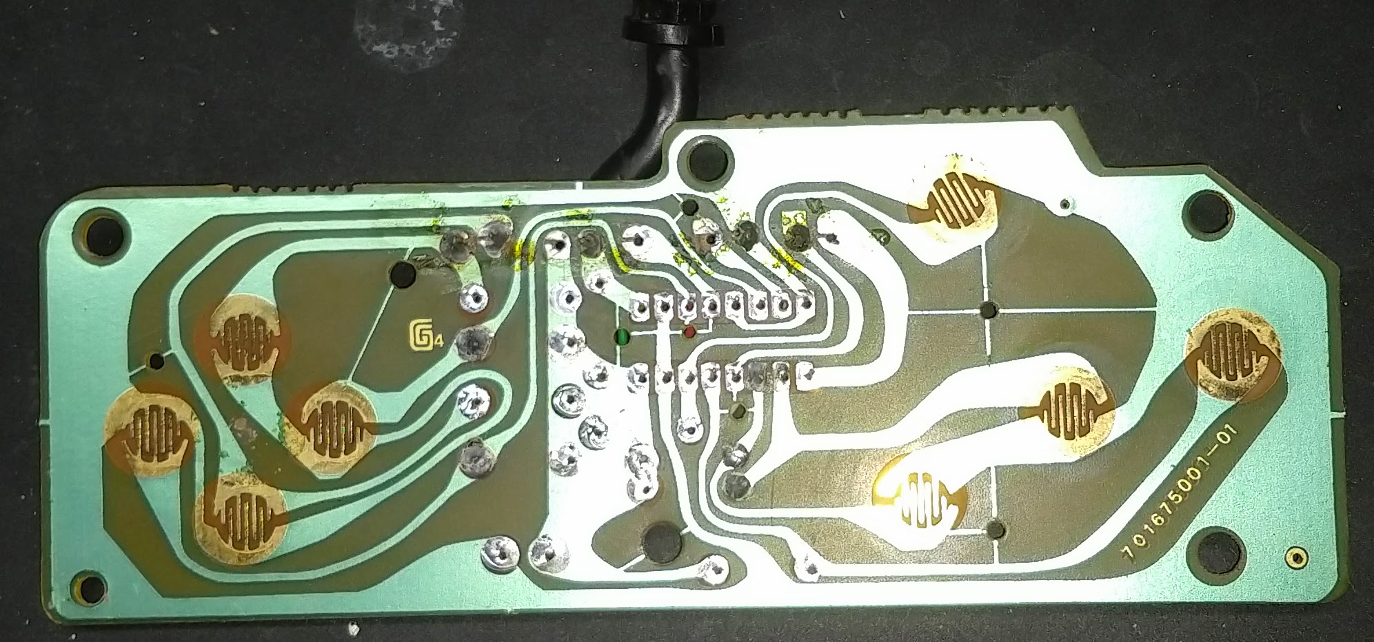
Here is a shot of my rewiring. Use a continuity tester to map out what color wire connects to which pin function on the Tomy.
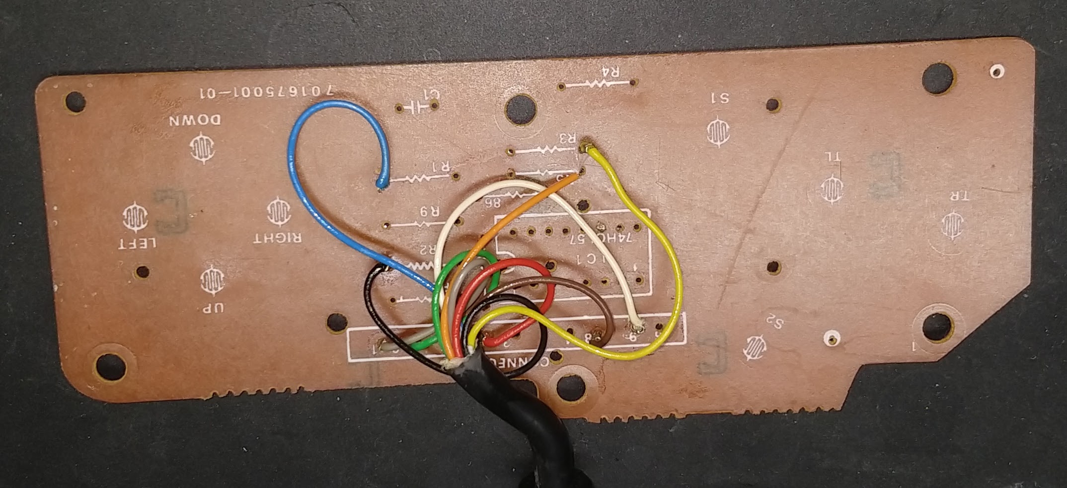
In my case, the color coding is:
| color | function |
|---|---|
| grey | up |
| green | down |
| red | nc |
| brown | player 1 |
| white | nc |
| black | right |
| blue | left |
| orange | SL |
| yellow | SR |
Solder the leads into circuit pads that connect to those functions on the pcb. SL to button ‘A’, and SR to button ‘B’. The direction to their d-pad correspondent. And player 1 to the common/ground on the pcb that leads to all the buttons.
In the end, we are just re-using the PCB as a bunch of switches.
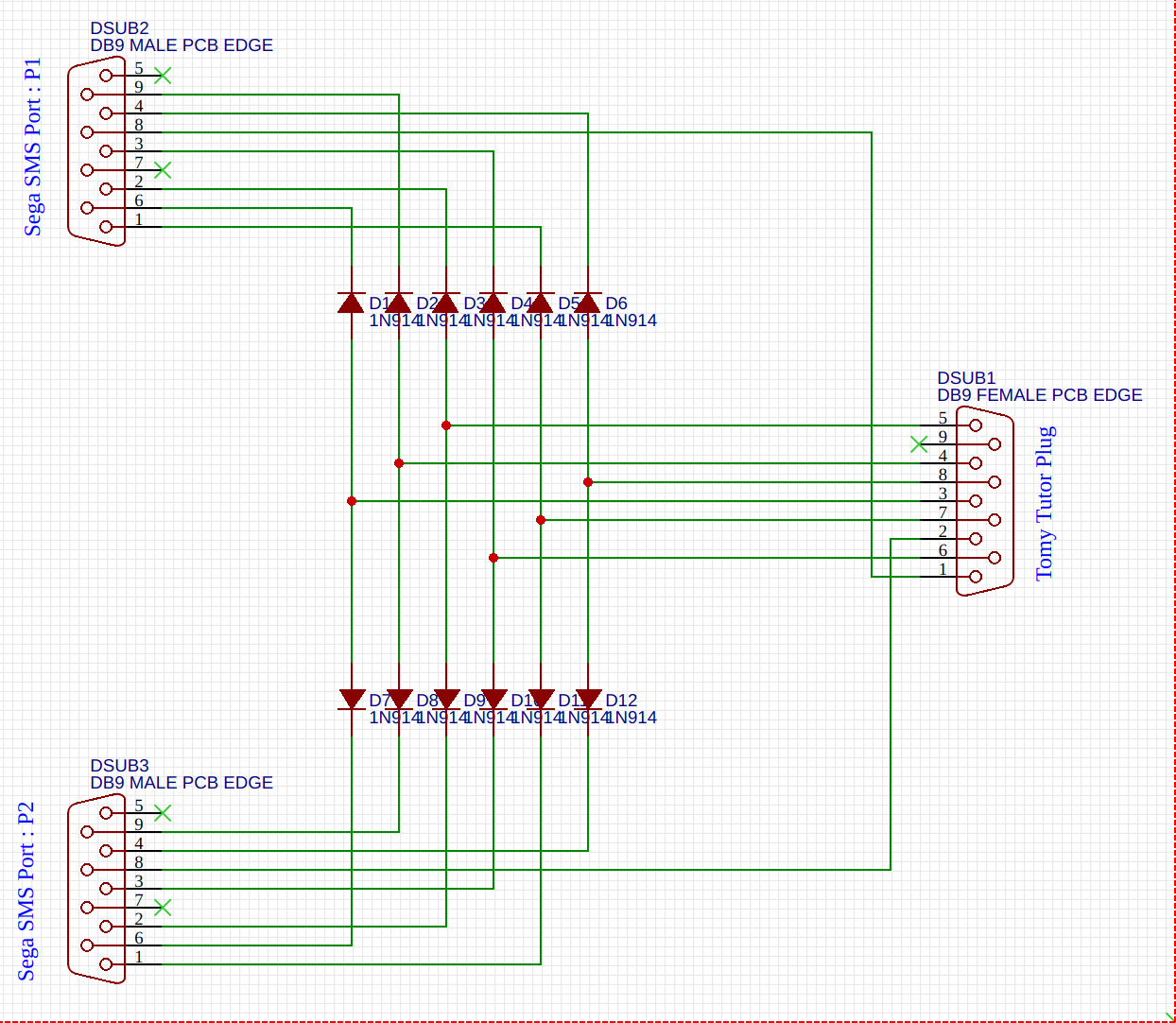
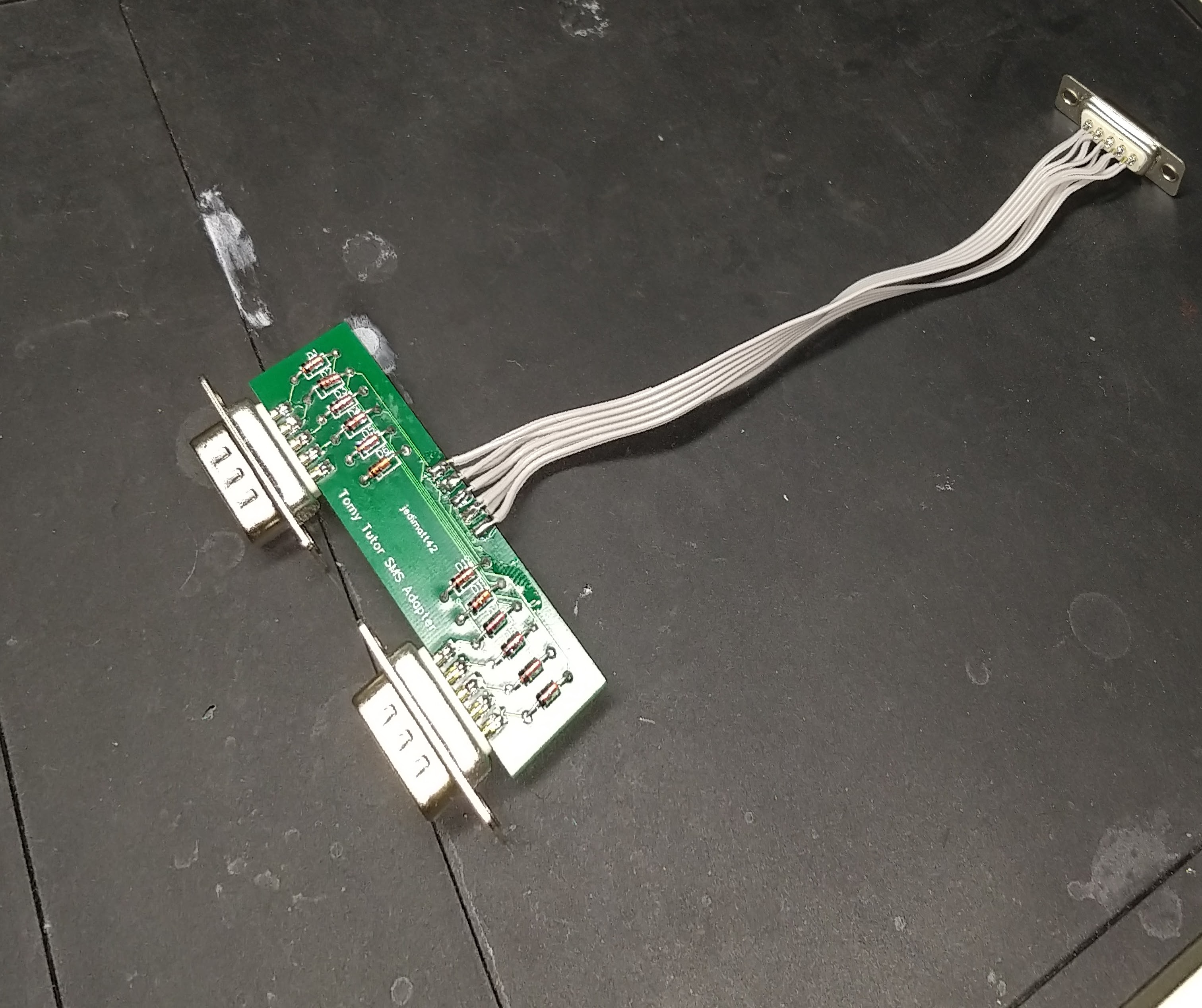
Sega SMS gamepad adapter
This schematic should work for allowing 2 Sega Master System controllers to work with the Tomy Tutor controller port. If a game only needs SL ( select-left ) then you could also use an Atari style single button joystick.
Someday
The Tomy Tutor is quite a marvel of simplicity. Just a TMS9995, sound chip, TMS9918 VDP, some ram, and rom, and you have a computer… There are no complicated PPIs or General IO 9901 chips for joystick and keyboard. Just some comparators and decoders, creatively hooked up to the IO mechanism of the TMS9995.
Someday, I’d like to decode the OS ROMs for the Tutor, and understand how much of the 4A architecture they borrowed, and what it would have taken to pull off the use of a 4A’s peripheral expansion box and peripherals, as was advertised but never realized.