This project is a keyboard adapter, allowing use of a USB keyboard with the TI-99/4a Home Computer. The adapter consists primarily of “off the shelf” arduino style components.
This was inspired by Tursi’s PS/2 keyboard adapter, the key mapping available in Classic99, and the Rave99 XT keyboard adapter from my youth.
The project has been discussed in this thread on Atariage.
All of the necessary Arduino SDK source and circuit board design are available at Github jedimatt42/TI-99-usb-keys.
I have tested the board with Logitech Nano Receiver wireless USB keyboard model K750. Also, I have tested with a cheap USB wired keyboard from Insignia.
This supports the 101-key keyboards in USB ‘boot’ protocol. That does place a restriction, preventing it from supporting special media keys and internet shortcut keys available on many ‘multimedia’ keyboards.
In general, it works like a TI keyboard, press ALT-P will produce a doublequote character. But so will pressing the now standard shift-quote key sequence. The mapping is copied from Tursi where the ‘boot’ protocol supports reading the key.
The internal keyboard remains operational.
Mapping:
- Caps-lock & Num-lock on at power up.
- Scroll-lock off at power up.
- Alt -> Fctn
- F1-F9 -> Fctn 1-9
- F10 -> Fctn 0
- F11 -> Ctrl 1
- F12 -> Ctrl 2
- Esc -> Fctn 9
- Arrow keys -> Fctn S,D,E,X
- with scroll-lock on, arrow keys are just S,D,E,X without Fctn
- Backspace -> Fctn S
- Home -> Ctrl U
- End -> Ctrl V
- Del -> Fctn 1
- Ins -> Fctn 2
- Pgup -> Fctn 6
- Pgdn -> Fctn 4
- Break -> Fctn 4
- Tab -> Fctn 7
- Num-lock does the logical thing to the number pad.
- Ctrl-Alt-Delete will reboot/reset the keyboard adapter.
Notes
While you can hold modifiers down, during power up, the adapter board may not be ready yet, and the TI may miss them.
Fctn-Equals has special release handling. I think the TI polls for Fctn-Equals too fast ‘boot looping’ if you will, interrupting the teensy too frequently for it to process the key release.
It works quite well with Micro-Pinball which is known to have trouble holding the flippers on the Rave99 adapter. I have however observed that sometimes it has issues with the tight polling loop in this game. Pressing Ctrl-Alt-Delete ( I swear this doesn’t run windows ) has proven to sync things up (my Teensy software is very interrupt driven), making gameplay reliable afterwards. I haven’t seen the same issue in any other software.
G1,G2,G3
There are 3 GPIO pins on the adapter board, that can be used to control other circuits. The latest firmware has them each mapped to Ctrl-Alt sequences:
- G1 -> Ctrl-Alt-F10
- G2 -> Ctrl-Alt-F11
- G3 -> Ctrl-Alt-F12
The firmware is configured so that when the key sequence is released, the pin is connected to ground for 25 milliseconds. At other times, they are ‘floating’. This is handy for connecting the to TMS9900 CPU pin 6 to create a hard reset button. It should also work for the load-interrupt on the CPU pin 4, although the duration may need to be adjusted for the load-interrupt. The reset has been tested, but the interrupt has not as of yet.
And if you have an imaginative use for the 3rd GPIO pin, please share.
Building the board
Required components:
- Teensy 3.1 or 3.2
- UHS mini pro
- 10uf aluminum electrolytic capacitor
- 52 pins worth of 2.54mm SIL IC Connector (round through hole style)
- Digi-Key
- 5 pins of 2.54mm SIL header
- 16 pins (2x8) 2.54mm of Dual right angle header
- Digi-Key note: updated link, previouly linked to wrong item
- 4cm of fine wire. I used 30awg, but 26awg should work.
- 1(one) 2X8 16P 2.54mm Dual Rows IDC Sockets for Flat Ribbon Cable, 16 Pins FC Female Connector
- 12inches of 16pin flat ribbon cable.
- Header lead
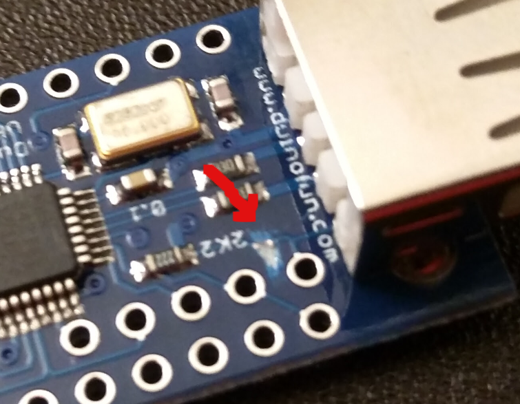
The UHS mini USB host shield must be modified. They ship with the +3.3v connected to the USB port’s +5v output pin. This isn’t expected to work for our application. Luckily the board is designed to easily cut the trace connecting the +3.3v, and solder a lead in that provides +5v.
Loading the firmware
If you get the Teensy from me, I will have pre-loaded the firmware. But the device can be updated before and after installation to the TI-99/4a console.
You will need to install the Arduino SDK, the Teensy for Arduino SDK.
1st, install the Arduino software:
Run the installer, accepting all the defaults.
2nd, install the Teensy 3.x sdk addon for Arduino. You will need to run the installer As Administrator on Windows.
Run the installer, accepting all the defaults.
Download the precompiled firmware image from my downloads page.
Unzip that image, and there will be a TI99USBKeys.ino.TEENSY31.hex file. This is compatible with a Teensy 3.1 or a Teensy 3.2.
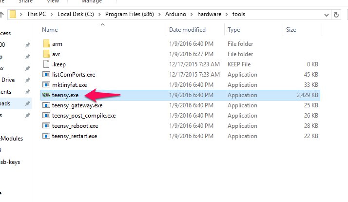
On a Windows system, find the Teensy Loader, and run it. It should be here:
If the TI 99 USB Keys adapter is already installed in the TI, then you must have the TI powered on while programming the adapter. When the adapter is re-programmed, it may trigger an errant keypress or a ‘reset’ if one of the G1,G2,G3 pins is connected to the TI. For that reason, it is best to be just sitting at the TI title screen.
A USB keyboard should be connected to the adapter as well during programming, or the adapter will be rebooting periodically and potentially miss the request to load the new firmware.
Connect a USB micro cable from the PC to the programming port on the TI 99 USB Keys adapter.
Then in the Teensy Loader, open the .hex file:


Click the grey/blue auto button if it is not set active default. Then use the software tool to reboot the Adapter. Watch the Teensy Loader window to see the update happen.

After a couple blah-bleeps from windows, your TI 99 USB Keys adapter should now be updated. Unplug the USB micro programming cable, and enjoy.
The code
The arduino project code is here: TI-99-usb-keys/TI99USBKeys
To work with the code, besides installing the SDK’s above, you will have to patch the Teensy SDK to add required feature.
Modify the core_pins.h and pins_teensy.c files for the Teensy to support the OPEN_DRAIN mode on the GPIO pins. See this post for details.
Installing
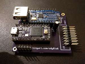
The best placement I found was in the roof of the TI Console case, above the AV connector or RF Modulator port. There are 2 ports on the adapter. The small USB client port is for reprogramming the Teensy. The USB host port is where your keyboard device plugs in. It is a good idea to expose both ports, as it is early days, and a software update for the Teensy may be necessary.
To attach the board, I used Scotch 3M Outdoor mounting tape. This stuff is strong, and gets stronger with time. You can see in the pictures, that I used 2 layers of the tape to get above the pins in the bottom of the board.
It is also necessary to tap the TI internal power supply to power the unit. I use two leads from a long bit of ribbon cable and solder them onto the TI powersupply’s ground and +5v output leads directly. Then I attach a header connector to the other end. The power pins on the board are well labelled on the 5 pin header on the board.
In addition to power, you have to connect it to the TI keyboard interface. Use 15 (or 16 pin ribbon cable) and an IDC connector on one end. On the TI end, I solder the ribbon cable to the back side of the original TI keyboard on joints for the 15 pin connector that goes to the mother board. Just tin each tip of your ribbon cable, then heat the joint, place the ribbon cable tip to the pin on the board, and remove the heat. Note, the orientation of the ribbon cable. The connector that goes to the TI motherboard has a red or highlighted end that is pin 15, not pin 1. Just make sure you match pin 15 to the IDC connector. Pin 16 on the IDC connector is not used, so you can’t just flip it over if you get it wrong.